Vagrant and Ruby: Creating multiple VMs programmatically

Vagrant is an excellent tool to quickly spin up a (Linux) VM to test all kinds of things: a new distribution, a configuration management tool, a new version of a software, you name it.

But Vagrant can do more: you can describe multiple VMs and their configuration in a single Vagrantfile. I’ve been using Vagrant for many years to develop various applications and test and verify deployments, and being able to spin up a small, but otherwise complete cluster is a godsend.

Manually defining multiple VMs

A simple example might look like this (directly stolen from the documentation):

Vagrant.configure("2") do |config|
config.vm.provision "shell", inline: "echo Hello"

config.vm.define "web" do |web|
web.vm.box = "apache"
end

config.vm.define "db" do |db|
db.vm.box = "mysql"
end
end

This Vagrantfile creates two VMs: one for MySQL, and another for Apache. This works well if the VMs you’d like to create are quite different from each other, and you need to configure them in significantly different ways.

Creating multiple similar VMs, and a problem

But sometimes, the cluster you’re setting up consists of multiple VMs that are very similar, or even identical, in configuration. I am working on trying out k3s together with Rook, MetalLB, and a current version of Traefik. For a minimal cluster with k3s and Rook Ceph, three nodes are needed. The first node, the k3s master, has a lot of configuration, but the additional nodes basically only need k3s installed; all configuration will be handled by k3s. So a naive approach could look like this:

Vagrant.configure("2") do |config|
config.vm.define "master" do |master|
master.vm.box = "debian/buster"
master.vm.network "private_network", ip: "192.168.33.10"
 master.vm.provision "shell", path: "provision-master.sh"
end

for i in 1..2
config.vm.define "node-#{i}" do |node|
node.vm.box = "debian/buster"
node.vm.network "private_network", ip: "192.168.33.#{10+i}"
node.vm.provision "shell", path: "provision-node.sh", args: [ i.to_s ]
end
end
end

The first VM is the master, the second and third are created identically with a for loop. In both blocks, a second network interface is added as a VirtualBox Host-Only network, so the cluster nodes can communicate with each other, and the host can access each node directly. The provision-node.sh will also receive the index variable so it can adjust names and objects to the node that is currently being provisioned.

When you vagrant up this configuration, you will be surprised to see that both node-1 and node-2 will received the IP address 192.168.33.12, and provision-node.sh will be called with 2 in both cases.

What’s happening?

To understand why Vagrant is misreading our intentions, we have to dive into Ruby a little bit. Vagrant is implemented in Ruby, and the Vagrantfile is in fact a Ruby program. The line

config.vm.define "node-#{i}" do |node|

defines a Ruby block (everything from do to the following end line) that is passed to the define method of the vm object of the config object. The block parameter |node| is provided by the define method when the block is executed. Inside the block, you can access properties of the node object, such as the vm object, and set values or call methods, to create the configuration that you need.

Also, the block has access to the variables that are defined in the main program. That’s why we can use Ruby string interpolation to format the node name ("node-#{i}") or the IP address ("192.168.33.#{10+i}") by using the loop variable i. So if this is all as it should be, why has the loop variable 2 as a value in both loops? When we look at the output of vagrant status, we see three VMs, each with it’s own unique name:

Current machine states:
master                    not created (virtualbox)
node-1                    not created (virtualbox)
node-2                    not created (virtualbox)

The reason the loop variable has the same value inside the block for both iterations is when the block is executed. You can be forgiven thinking that the code should execute right where it appears in the code: inside the loop, when config.vm.define is called. However, that is only when it is defined. Vagrant will run the Vagrantfile program and construct an internal configuration from it, collecting the blocks for various properties. Only when the complete definition of the configuration has been collected, these blocks are executed and their results taken into consideration.

By the time the blocks for each of the two nodes are executed, the for loop has completed, and the loop variable simply has the last value. Since the variable is only resolved when the block is executed (not when it is defined), the value is 3 for both versions of the blocks. This is really surprising for many people not familiar with this Ruby idiom and the way it is often used. While other languages have the capability to store closures for later use, I have not seen this pattern there, only in Ruby-based applications.

Creating a configuration object

So, how can we overcome this? Since the loop variable is referenced in both instances of the block definition, but doesn’t have the right value by the time the code finally is executed, we somehow need to make sure we have a different variable for each round. One way to achieve this is to define our own config class, and create a config object for each iteration that stores all the info that we’re interested in, and can define the block in such a way that only the config class instance is referenced.

Let’s look at the example:

class Cfg
def initialize(i)
@name = "node-#{i}"
@ip = "192.168.33.#{10 + i}"
end

def configure(config)
config.vm.define @name, primary: @primary do |v|
v.vm.hostname = @name
v.vm.network "private_network", ip: @ip
end
end
end

Vagrant.configure("2") do |config|
# ...

for i in 1..2
cfg = Cfg.new(i)
cfg.configure(config)
end
end

First, we define a Ruby class Cfg that receives two properties, name and ip, when the instances is created (the initialize method). Then, the configure method runs the Vagrant code and uses the instance properties. Finally, in the for loop, we create a new instance of the Cfg class for each iteration, and call each instances configuration method.

Further reading

The code in this post is simplified. If you would like to see the real-world code that stands up a k3s cluster with additional components, head over to github.com/stblassitude/k3s-rook.
Enabling backwards compatibility in OpenVPN

If your OpenVPN client is showing errors like

AUTH: Received control message: AUTH_FAILED,Data channel cipher negotiation failed (no shared cipher)

after the server has been upgraded to OpenVPN 2.5, you might need to configure fallback options. Since OpenVPN 2.4, client and server will try to negotiate the best ciphers that are available to both sides. In OpenVPN 2.5, the automatic fallback to a standard cipher has been disabled (I think), but it can be reenabled on the server with the data-ciphers-fallback directive. You need to make sure that both server and (pre 2.4) clients use the same cipher. The 2.3 and earlier default is BF-CBC, which is considered outdated and weak.

I have some older OpenWrt based routers installed at some family members’ homes (for easier remote support), which I cannot easily upgrade remotely. So I had to update both by OpenVPN 2.5 server config by adding this line:

data-ciphers-fallback AES-256-CBC

And on the client side, I added this line to the config section in /etc/config/openvpn:

   option cipher 'AES-256-CBC'

After restarting both the server and the clients, the connections are re-established again.

If you’re getting error message like this on the server:

client.example.com/192.168.23.45:49263 Authenticate/Decrypt packet error: cipher final failed

The problem is likely that the fallback cipher on the server does not match the cipher on the client. Double check that the data-ciphers-fallback and cipher options specify the same value.

This page shows the matrix of supported ciphers between 2.3, 2.4, and 2.5.

PC Engines APU2C4

Installing FreeBSD on PC Engines APU2

PC Engines APU2C4

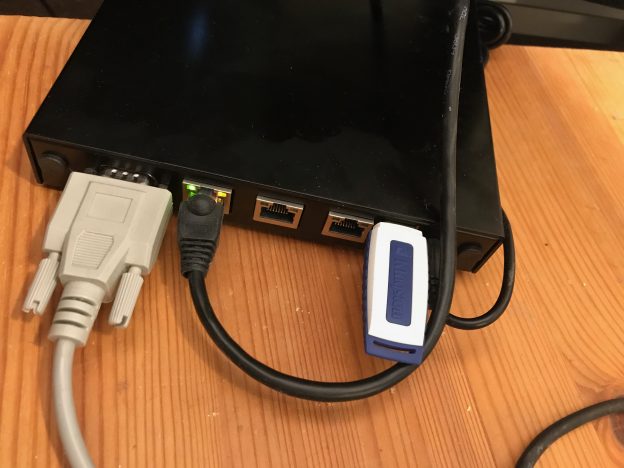
The PC Engines APU2C low-power network computer on my desk, with serial console, the first ethernet port and a USB stick connected.

PC Engines has been producing small, low-power systems with AMD CPUs for a long time. Among the great features for building your own router are built-in serial console and multiple quality Ethernet controllers. For a project I selected the apu2c4, a system with three gigabit Ethernet ports and 4 GB of RAM. Together with a small M2 SSD module, you have a decently powerful machine to run as a router. In fact, it has enough capacity to run some applications as well, or even small VMs if you’re so inclined!

Installing FreeBSD

Installing FreeBSD on the APUs is fairly straightforward; however, a small number of gotchas might trip you up. Here’s how I managed to complete the install, and update the APU firmware once I had FreeBSD installed.

  1. Download the FreeBSD memstick installer image. I used my closest FreeBSD mirror to download FreeBSD-11.2-RELEASE-amd64-memstick.img.
  2. Copy the image to a USB stick that is at least as large as the image; 1 GB should be sufficient. I had trouble when I did the copying on my Mac with the resulting stick not working properly; using a FreeBSD box did the trick for me.
  3. Before booting from the USB stick, mount the UFS partition on a FreeBSD machine. For 11.2, that’s da0s2a; for other releases, it might be different. You can use gpart list to identify the UFS partition to mount.
  4. Add the following lines to /mnt/boot/loader.conf to properly enable just the serial console, and give the USB subsystem enough time to attach the USB stick:
  5. vfs.mountroot.timeout="10"
    comconsole_speed="115200"
    console="comconsole"
  6. Unmount /mnt and move the stick to the APU.
  7. Connect a serial terminal to the APU console port; I usually use an USB dongle and a null modem cable or adapter, and my own simple serial console program or cu(1), using 115200 baud.
  8. Boot from the USB stick and install FreeBSD as you would on any other PC. Before you reboot:
  9. Make sure to add the console and comconsole_speed variables to /boot/loader.conf on the installed system on the APU as well. Unless you add them, you won’t be able to log in to the console.

If you forget to edit /boot/loader.conf, not all is lost: you can change the settings during boot. But because the loader detects both the serial console and a keyboard (although the APU has no support for a keyboard or built-in graphics), it is somewhat cumbersome, as the console output will be screwed up.

Updating the BIOS

The APUs use CoreBoot as their BIOS. PC Engines has ready to use CoreBoot images on their own GitHub page. You can update the BIOS using flashrom, a command line tool to program firmware devices across many devices and platforms.

To update the APU BIOS:

  1. Download the correct CoreBoot image for your model of APU from pcengines.github.io, directly to the APU. I picked apu2 v4.8.0.1, which was the newest at the time of this post.
  2. Extract the firmware file:
  3. $ fetch http://pcengines.ch/file/apu2_v4.8.0.1.rom.tar.gz
    apu2_v4.8.0.1.rom.tar.gz                      100% of  852 kB 4100 kBps 00m00s
    $ tar xf apu2_v4.8.0.1.rom.tar.gz 
    $ ls -l
    total 862
    -rw-r--r--  1 stb  wheel  8388608 Jun  8  2018 apu2_v4.8.0.1.rom
    -rw-r--r--  1 stb  wheel       52 Jun  8  2018 apu2_v4.8.0.1.rom.md5
    -rw-r--r--  1 stb  wheel   873087 Jun 26  2018 apu2_v4.8.0.1.rom.tar.gz
  4. Install the utility:
    $ sudo pkg install flashrom
    Updating FreeBSD repository catalogue...
    FreeBSD repository is up to date.
    All repositories are up to date.
    Checking integrity... done (0 conflicting)
    The following 1 package(s) will be affected (of 0 checked):
    
    New packages to be INSTALLED:
            flashrom: 1.0
    
    Number of packages to be installed: 1
    
    Proceed with this action? [y/N]: y
    [1/1] Installing flashrom-1.0...
    [1/1] Extracting flashrom-1.0: 100%
  5. Check that flashrom can talk to your motherboard OK:
  6. $ sudo flashrom -p internal
    flashrom v1.0 on FreeBSD 11.2-RELEASE (amd64)
    flashrom is free software, get the source code at https://flashrom.org
    
    Using clock_gettime for delay loops (clk_id: 4, resolution: 2ns).
    coreboot table found at 0xcfde9000.
    Found chipset "AMD FCH".
    Enabling flash write... OK.
    Found Winbond flash chip "W25Q64.V" (8192 kB, SPI) mapped at physical address 0x00000000ff800000.
    No operations were specified.
  7. Verify the version currently installed:
  8. $ sudo dmidecode -t bios
    # dmidecode 3.1
    Scanning /dev/mem for entry point.
    SMBIOS 2.7 present.
    
    Handle 0x0000, DMI type 0, 24 bytes
    BIOS Information
            Vendor: coreboot
            Version: v4.8.0.1
            Release Date: 20180608
            ROM Size: 8192 kB
            Characteristics:
                    PCI is supported
                    PC Card (PCMCIA) is supported
                    BIOS is upgradeable
                    Selectable boot is supported
                    ACPI is supported
                    Targeted content distribution is supported
            BIOS Revision: 4.0
            Firmware Revision: 0.0
  9. Program the new version to the flash chip:
  10. $ sudo flashrom -p internal -w apu2_v4.8.0.1.rom
  11. If flashrom complains about the image not matching the mainboard, you need to force the programming as suggested in this forum post.
  12. Reboot the APU to activate the new firmware.

(Astute readers will notice that the above output already shows version 4.8.0.1 being installed; I took that output after successfully upgrading.)

I tried to update the BIOS using the procedure suggested by PC Engines, using TinyCore, but I had trouble creating a TinyCore USB stick. Luckily I came across this BSD Foren post and realised that I could just use FreeBSD directly.

How to set the frame rate for a project in iMovie 10.4

If you use different devices to record video, you might have come across “jittery” playback of some clips: if the project has a frame rate different from the clip you’re adding, iMovie adapts by removing frames, or duplicating them, depending on whether the clip frame rate is higher or lower than the project frame rate.

So how does iMovie determine which frame rate to use for a project? It sets the project frame rate when you add the first clip to the project. However, it only does that if you click the plus icon! If you drag the clip from the media browser to the timeline, it keeps it’s default, which for me (in Europe) appears to be 24 frames per second.

Screencast showing clicking and dragging of clips in iMovie

Click + to add the first clip to set the project frame rate

Since there is no way to change the frame rate after adding the first clip, make sure you drag an appropriate clip in to the time line first thing. The only way I found to check if the correct frame rate has been set is to export the project and check with QuickTime or VLC.

Fixing the Wemos D1 Mini DHT22 Shield

The Wemos D1 Mini DHT shield V1 is a simple board that hooks up a DHT11 temperature and humidity sensor to the ESP8266. The data line from the sensor is connected to pin D4, which the ESP8266 uses during boot as a second TXD line. (This is why the LED flashes as you upload a new sketch: the LED is connected to D4.)

At least for the boards I’m using, this confuses the sensor completely, and it will not react to the ESP8266 trying to read data from it.

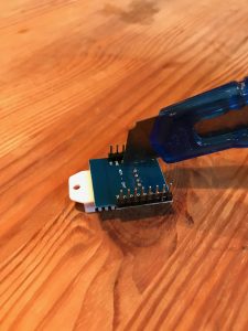
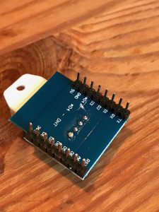
The only way to fix this then is to move the DHT22 data line to another pin. First, I cut the trace on the bottom of the PCB:

Cutting the trace between DHT22 and D4

This is how it looks like after the cut:

Trace between data line of the DHT22 and pin D4 is cut

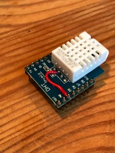
Finally, I connected the data line from the DHT22 to pin D0:

DHT22 data line connected to D0

With the Arduino sketch adjusted to use pin D0 instead of D4, the sensor can now be read reliably.

p.s. It is possible that this problem is limited to clone boards that use the DHT22 instead of the DHT11. I now see that Wemos has discontinued the V1 version of this board. The current version uses a DHT12 sensor that communicates via I2C.

Hooking up Harmony Hub and generic ZigBee Lights to HomeKit

Home automation seems to be the rage this christmas, with gadgets to control lights, heating and entertainment systems wirelessly, maybe even with only your voice.

I’ve been using Logitech’s Harmony Hub for many years now, and are very happy being able to switch on all devices needed and set them to the right channels: the TV, the surround receiver, the TV and an Apple TV, Fire TV or Bluray player, with single button press on a single remote.

Harmony Hub isn’t supported by Apple’s HomeKit, but so far, that wasn’t really a concern, since I wasn’t using anything else that would be able to be controlled by HomeKit. But in December, I broke down and got a bunch of Philips Hue lights. Naturally, tying Hue and Harmony together became a challenge.

I also have a number of light fixtures that Philips has no bulbs for; I decided to get an Osram Lightify Smart Plug to be able to at least turn the light off and on through the system. While it’s simple to connect the Smart Plug to the Hue controller, Philips somehow fails to offer up 3rd-party devices to either HomeKit or Hub. (Ikea Tradfri components seem to suffer the same fate.)

So I started looking around, to find a way to control everything through a single interface. It seems that HomeKit together with homebridge manages to do exactly what I want: offer all devices connected to the Hue hub to HomeKit (through homebridge-hue), and allow me to control the Harmony Hub (through homebridge-harmonyhub).

Here’s how I got this all working in FreeBSD.

Installing homebridge on FreeBSD

Creating a user

homebridge is a daemon process that mediates between HomeKit, Hue and Harmony. As such, it needs to run permanently. For security reasons, we do not want to run homebridge as root, but as a less privileged user homebridge. To create the user, I used vipw and consulted /usr/ports/GIDs to look for an id in the range below 1000 that is not yet used by any port. Instead of vipw, you can use adduser(1). I gave the user /usr/sbin/nologin as a shell since we’re never going to log in directly as a user.

Installing packages

There is no FreeBSD port for homebridge, but the installation is relatively straightforward. The installation instructions for homebridge insist that the NPM must be installed globally; I briefly tried to install locally, but couldn’t get it work.

Let’s start with the prerequisites, and a hack:

# pkg install npm-node8 avahi-libdns
# ln -s /usr/local/include/avahi-compat-libdns_sd/dns_sd.h /usr/local/include

The FreeBSD port for avahi-libdns puts the include file into its own subdirectory (so it won’t conflict with mDNSResponder), but the NPM packages expect it to be in /usr/local/include. The easiest way to fix this is to create the symlink. Since I’m running avahi, I have not investigated how to run homebridge with mDNSResponder.

After this, we can starting installing the NPM packages:

# npm install -g mdns
# npm install -g --unsafe-perm homebridge
# npm install -g homebridge-hue homebridge-harmonyhub

As of homebridge-harmonyhub 0.2.1, you’ll need to hack the broadcast address that it uses to find the Harmony Hub. Edit /usr/local/lib/node_modules/homebridge-harmonyhub/node_modules/harmonyhubjs-discover/lib/ping.js and change the address in line 9 to the appropriate broadcast address for the network that your Hub is connected to. For example:

this.address = '192.168.1.255';

Configuring Homebridge

Create a config file in the homebridge users’ home directory, as .homebridge/config.json. I created the initial file like this:

{
    "bridge": {
        "name": "Homebridge",
        "username": "CC:22:3D:E3:CE:30",
        "port": 51826,
        "pin": "031-45-154"
    },
    
    "description": "My Homebridge",

    "accessories": [
    ],

    "platforms": [
        {
            "platform" : "Hue",
            "name" : "Hue",
            "users": {
            },
            "lights": true,
            "nativeHomeKit": false,
            "sensors": true,
            "excludeSensorTypes": ["CLIPPresence", "Geofence"]
        },
        {
            "platform": "HarmonyHub",
            "name": "Hub",
        }
    ]
}

Then, start homebridge for the first time:

sudo -u homebridge homebridge

The output from this is important in two ways: homebridge-hue will connect to the Hue bridge, wait for you to press the button to authorise the pairing, and then display the username and token for this connection. You’ll need to copy the output and add it to the users key for the Hue platform entry in the configuration. You will need to restart homebridge for this config change to become effective.

Also, the terminal output will show a QR code you can use to connect homebridge as a bridge to HomeKit, using the Home app on your phone or iPad. You can also enter the code manually, in this example the code is 031-45-154.

Running homebridge as a daemon

There’s (at least) two ways to run homebridge in the background: using tmux(1) or daemon(8)

WIth tmux(1) (or screen(1)), you can run a terminal session independent of the current login. You can detach from that session at any time, and it will continue to run; you can also re-attach at a later time. This allows you to start homebridge, observe all the log output, and then detach from the session, keeping it running. If you need to look at the log output, you can reattach. This is most useful while you’re optimising the configuration, or trying out additional plugins.

For a more production-oriented setup, you can use daemon(8) and an rc(8) script. The following script /usr/local/etc/rc.d/homebridge creates a service homebridge that you can enable and disable from rc.conf(5):

#!/bin/sh
#
# PROVIDE: homebridge
# REQUIRE: NETWORKING SYSLOG
# KEYWORD: shutdown
#
# Add the following lines to /etc/rc.conf to enable homebridge:
#
#homebridge_enable="YES"

. /etc/rc.subr

name="homebridge"
rcvar="homebridge_enable"

load_rc_config $name

: ${homebridge_user:="homebridge"}
: ${homebridge_enable:="NO"}
: ${homebridge_facility:="daemon"}
: ${homebridge_priority:="debug"}

command="/usr/local/bin/${name}"
procname="/usr/local/bin/${name}"
home="$(eval echo ~${homebridge_user})"

pidfile="/var/run/${name}.pid"

start_cmd="${name}_start"

homebridge_start() {
	/usr/sbin/daemon -S -l ${homebridge_facility} -s ${homebridge_priority} \
		-u ${homebridge_user} -p ${pidfile} \
		/usr/bin/env -i \
		"HOME=${home}" \
		"PATH=/usr/local/bin:${PATH}" \
		$command
}

run_rc_command "$1"

Now the last thing I need to figure out is which Siri commands to use to activate a scene. Then I can switch on the entertainment center and dim the lights with a single voice command!

OpenStack: fixing “No socketless chef-zero server”

I’ve started playing with various incarnations of “in a box” OpenStack setups to familiarize myself with OpenStack, among them DevStack and Ubuntu OpenStack. The OpenStack Chef Repo looks promising to me, as it gives you a good starting point, but can easily be extended to more complex lab setups, or even full productions environments.

The only problem? This error:

$ git clone https://github.com/openstack/openstack-chef-repo
$ export REPO_OS=centos7.1
$ cd openstack-chef-repo
$ chef exec rake berks_vendor
$ chef exec rake aio_neutron
chef exec chef-client --force-formatter -z vagrant_linux.rb aio-neutron.rb
[2015-08-09T23:41:58+02:00] INFO: Started chef-zero at chefzero://localhost:8889 with repository at /Users/stb/working/xxx/openstack-chef-repo
  One version per cookbook

[2015-08-09T23:41:58+02:00] INFO: Forking chef instance to converge...
Starting Chef Client, version 12.3.0
...
[2015-08-10T00:02:19+02:00] INFO: Converging controller because 'converge true' is set ...
[2015-08-10T00:02:19+02:00] INFO: Port forwarded: local URL chefzero://localhost:8889 is available to 127.0.0.1 as chefzero://localhost:8889 for the duration of this SSH connection.
[2015-08-10T00:02:19+02:00] INFO: Executing sudo chef-client -l info on vagrant@127.0.0.1

    [controller] [2015-08-09T22:02:18+00:00] INFO: Forking chef instance to converge...
                 Starting Chef Client, version 12.4.1
                 [2015-08-09T22:02:18+00:00] INFO: *** Chef 12.4.1 ***
                 [2015-08-09T22:02:18+00:00] INFO: Chef-client pid: 13637
                 
                 ================================================================================
                 Chef encountered an error attempting to load the node data for "controller"
                 ================================================================================
                 
                 Unexpected Error:
                 -----------------
                 ChefZero::ServerNotFound: No socketless chef-zero server on given port 8889
                 
                 
                 Running handlers:
                 [2015-08-09T22:02:20+00:00] ERROR: Running exception handlers
                 Running handlers complete
                 [2015-08-09T22:02:20+00:00] ERROR: Exception handlers complete
                 Chef Client failed. 0 resources updated in 2.194757362 seconds
                 [2015-08-09T22:02:20+00:00] FATAL: Stacktrace dumped to /var/chef/cache/chef-stacktrace.out
                 [2015-08-09T22:02:20+00:00] ERROR: No socketless chef-zero server on given port 8889
                 [2015-08-09T22:02:20+00:00] FATAL: Chef::Exceptions::ChildConvergeError: Chef run process exited unsuccessfully (exit code 1)
[2015-08-10T00:02:23+02:00] INFO: Completed chef-client -l info on vagrant@127.0.0.1: exit status 1

I’m far from an expert in Chef, so it took me a bit of searching and experimenting. Luckily, the solution is rather simple:

$ chef gem list -d '^chef-provisioning$'

*** LOCAL GEMS ***

chef-provisioning (1.1.1)
    Author: John Keiser
    Homepage: http://github.com/chef/chef-provisioning/README.md
    Installed at: /opt/chefdk/embedded/lib/ruby/gems/2.1.0

    A library for creating machines and infrastructures idempotently in
    Chef.
$ chef gem update chef-provisioning
Updating installed gems
Updating chef-provisioning
Fetching: chef-provisioning-1.3.0.gem (100%)
WARNING:  You don't have /Users/stb/.chefdk/gem/ruby/2.1.0/bin in your PATH,
	  gem executables will not run.
Successfully installed chef-provisioning-1.3.0
Gems updated: chef-provisioning
$ chef gem list -d '^chef-provisioning$'

*** LOCAL GEMS ***

chef-provisioning (1.3.0, 1.1.1)
    Author: John Keiser
    Homepage: http://github.com/chef/chef-provisioning/README.md
    Installed at (1.3.0): /Users/stb/.chefdk/gem/ruby/2.1.0
                 (1.1.1): /opt/chefdk/embedded/lib/ruby/gems/2.1.0

    A library for creating machines and infrastructures idempotently in
    Chef.

The next version of ChefDK will likely come with this updated version of chef-provisioning, but until then, this should do the trick.

Getting started with the Arietta G25 board

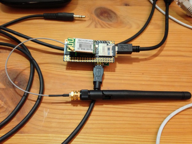
This weekend, I received my ACME Arietta G25 Atmel ARM board, and tried to get it going with my Mac. I ordered the “plain” version with 128 MB RAM, as well as one with 256MB RAM, as well as Wifi boards and the DPI debug board.

After soldering in the necessary posts, I attached the DPI board and verified that my Mac has the right FT232 driver to access the console, no problems here.

I then fired up by Ubuntu VirtualBox machine and followed the instructions to build the Micro-SD-Card image. I then proceeded to boot successfully from the card.

IMG_2989

Through the console, I could get the Wifi card going; since I wanted to have support for more than a single network, I extended the configuration through wpa_supplicant.conf.

ACME has configured a Gadget driver to supply an Ethernet interface through the host port on the Arietta; in ACMEs configuration, this is set to offer both RNDIS and CDC EEM modes. Unfortunately, Mac OS X 10.9 doesn’t support either.

After some more reading, I decided to build my own kernel and modules. To get a Mac-compatible setup for the USB Gadget driver, run menuconfig, and navigate to

  • Device Drivers
  • USB support
  • USB Gadget Support (at the very bottom of the list)

For Mac compatibility, de-select the RNDIS support and the Ethernet Emulation Model (EEM) support under Ethernet Gadget.

I also chose to enable the Serial Gadget and the CDC Composite De
vice (Ethernet and ACM).

After building the kernel and replacing the files on the SD Card, I changed the module load line in /etc/network/interfaces to load the g_cdc module instead of the g_ether module, and added an entry in /etc/inittab for /dev/ttyGS0 to also have a console through the host port.

Debugging Java proxy settings

Java proxy settings are highly annoying. On Windows and Mac, Java does use the system proxy settings, but it doesn’t necessarily understand the same syntax as say IE or Safari/WebKit for the proxy exceptions. The end result is that you keep guessing why certain services deep inside your huge web application keep failing in mysterious ways.  On other platforms, you have to configure the proxy through system properties. Restarting a web application to test out configuration changes can take a long time.

While solving the problem might not be easy, at least I can help with debugging it, with a very simple one-liner: Java Proxy Check (GitHub, direct download link).

For java.net.URL and most other HTTP client code, Java 7 uses a class that can decide on a per-URL basis which proxy should be used: java.net.ProxySelector. javaproxycheck.jar can be run  from the command line to quickly test one or more URLs and see which proxy is selected for that URL:

$ java -Dhttps.proxyHost=proxy.example.com -Dhttps.proxyPort=3128 -jar javaproxycheck.jar http://www.example.com https://secure.example.com
http://www.example.com                   [DIRECT]
https://secure.example.com               [HTTP @ proxy.example.com:3128]

On Mac OS X and Windows, Java uses the system proxy configuration; on other systems, it optionally can use Gnome settings, but by default relies on system properties being set at startup, as documented in Networking Properties, Proxies.

nsupdate woes

Over the past three days, I’ve been trying unsuccessfully to set up a fresh name server (using Ansible and Vagrant) to play around with nsupdate and some potential middleware to automate updating DNS zones. Unfortunately, I couldn’t find any good documentation on all the specifics, just a lot of how-tos that somehow all did’t really work for me. I kept getting this error:

client 127.0.0.1#60530: request has invalid signature: TSIG example.com: tsig verify failure (BADKEY)

I will upload my Ansible role for this to Github shortly, but I felt it necessary to spare the next person the pain of getting it all to work.

To use nsupdate, you need to give bind a key, associate that with a zone, and then use that key with nsupdate. Sounds easy enough, right? What all the tutorials fail to mention is that the key files and the name of the key entries in named.conf are all significant.

First, you need to decide what to call your key. It doesn’t matter for which zones you will use it, or from which hosts you will run nsupdate, but you will need to pick a name and stick to it. You can’t change it later, you will need to create a new key if you don’t like the name.

$ dnssec-keygen -a HMAC-MD5 -n HOST -b 512 mysamplekey

This will create two files. You need both of them, and you can’t change the files’ names.

Next up, you need to add the key to named.conf, and allow requests signed by that key to update a zone (or more):

key "mysamplekey" {
    algorithm hmac-md5;
    secret "base 64 encoded key";
};

zone "example.com" {
    allow-update { key "mysamplekey"; };
    type master;
    file "dynamic/example.com";
};

It is important to remember that “mysamplekey” needs to be the exact same string as from the key generation!

Armed with this configuration, you should be able to update example.com:

$ nsupdate -k Kmysamplekey+123+45678
debug yes
server 127.0.0.1
zone example.com
update add foobar 10 A 192.0.2.1
send